• 2CL2H Power Frequency HV diodes 12KV 200mA 50-60Hz
  • 2CL2H Power Frequency HV diodes 12KV 200mA 50-60Hz
  • 2CL2H Power Frequency HV diodes 12KV 200mA 50-60Hz
  • 2CL2H Power Frequency HV diodes 12KV 200mA 50-60Hz
  • 2CL2H Power Frequency HV diodes 12KV 200mA 50-60Hz
  • 2CL2H Power Frequency HV diodes 12KV 200mA 50-60Hz

2CL2H Power Frequency HV diodes 12KV 200mA 50-60Hz

Products Main features:
1、Axial leaded connection.
2、High thermal conductivity epoxy compound molding.
3、Low internal resistance reduces energy loss.
4、Special passivation glue chip protection
5、Excellent discharge characteristics.
  • 2CL2H Power Frequency HV diodes 12KV 200mA 50-60Hz
  • 2CL2H Power Frequency HV diodes 12KV 200mA 50-60Hz
  • 2CL2H Power Frequency HV diodes 12KV 200mA 50-60Hz
  • Desciption

  • data sheet

  • Installation Guide

Product Overview

The 2CL2H is an axial-leaded rectifier built for the DC side of mains-frequency high-voltage supplies. It blocks up to 12 kV in the reverse direction and carries an average forward current of 200 mA, which puts it in the rectifying stage of equipment where the waveform is a rectified sine at 50 or 60 Hz rather than a switching edge.

That line-frequency role shapes the whole part. A power frequency diode is chosen for blocking capability, a stable forward drop and predictable reverse leakage; recovery time is not specified because it is not the limiting parameter in these circuits. Design teams use them in the high-voltage tanks of X-ray and DR generators, dental and panoramic imaging supplies, industrial NDT sets, DC high-voltage testers, electron accelerator supplies and transformer-driven multiplier strings.

Each of these high voltage diodes is a black molded cylinder with silver axial leads. Leads can be formed to a chassis or a board footprint before soldering, the body is small enough to sit inside a compact tank, and because the part is wired rather than surface-mounted, the joints can be inspected and reworked after assembly. A white band at one end marks the cathode.

HVDIODE has been building these parts since 2008, and the 2CL2 series is its power-frequency range, with several voltage classes sharing the same axial construction — where a design needs more blocking headroom than 12 kV, a higher-voltage member of the series is the part to specify. We are high voltage diode manufacturers, and the series, its package drawing and its test data all come from our own plant in Anshan.

Key Features

  • Axial leaded connection. Both leads exit the ends of the body, so an axial high voltage diode can be wired point to point, threaded through a PCB or fixed to a chassis before soldering. In oil-filled tanks and potted modules this is often easier than a surface-mount footprint, because the joint stays accessible for inspection and rework.
  • High thermal conductivity epoxy molding. The chip is encapsulated in an epoxy compound selected to move heat from the junction to the body surface and out along the leads. In an air-cooled build that molding is the main heat path; in oil it keeps the chip protected while the surrounding medium does the cooling.
  • Low internal resistance. Conduction losses stay small at the rated 200 mA, so a power frequency diode runs cooler in continuous DC duty and leaves more of the ambient range in reserve. That matters in supplies that run for hours rather than in short bursts.
  • Special passivation glue chip protection. The chip surface carries a passivation layer before encapsulation, which keeps the blocking junction away from moisture and ionic contamination. Reverse leakage stays predictable, which is what high voltage diode manufacturers look for in a measuring or imaging supply.
  • Excellent discharge characteristics. Multiplier strings, test sets and capacitor-discharge circuits expose the diode to fast-rising voltage and stored charge. The part behaves predictably under those conditions, so the waveform of the surrounding circuit stays as designed.
  • Readable polarity. The white band on the black body shows which end is the cathode, so orientation can still be checked once the module is potted or the chassis is crowded.

Operating Media & Heat Path

  • Insulating oil (recommended). Oil immersion gives a high voltage rectifier diode the strongest dielectric surroundings available and carries heat away from the body at the same time. It is the usual choice for X-ray tanks and oil-filled assemblies, and it lets a compact part work in a compact tank.
  • Insulating gas (recommended). Gas-filled housings suit high voltage diodes in builds that must stay dry and light. The gas has to be clean and dry, and the housing design has to keep the field away from sharp metal edges; settle the gas specification with whoever supplies the tank.
  • Secondary packaging or potting. Potted modules give good dielectric strength but can trap heat around the body. Check the thermal conductivity of the compound, and leave the leads some free length so heat can escape instead of soaking back into the module.
  • Exposed air with forced cooling. An air build is the hardest case. Air breaks down at lower stress than oil or gas, a small axial high voltage diode is more prone to discharge at the lead ends, and convection alone may not carry the loss away — add airflow and keep the assembly clean and dry.
  • Insulated electrodes in air. For an exposed-air installation, terminate both ends with insulated electrodes. That controls corona at the lead tips and keeps the discharge path away from the body surface.
  • Clearance and creepage. Judge the layout by the distance over the body surface and along the leads, not only by the gap through air. Longer lead runs and a stand-off from metal parts both raise the withstand of the finished assembly.
  • Give the body room. Mount the part where air can move across it rather than under sleeving or inside a tight wire bundle; a diode that cannot lose heat will not hold its rating for long.

Specifications

ParameterSymbolTest conditionsValue
Repetitive peak backward voltageVrrmTa = 25 °C, Ir = 2.0 µA12 kV
Peak working backward voltageVrwmTa = 25 °C, Ir = 2.0 µA12 kV
Average forward currentIf(AV)50 Hz half-sine wave, resistive load, Tbreak = 50 °C200 mA
Backward recovery timeTrrNot specified for this power frequency diode—
Surge forward currentIfsm0.01 s half-sine wave, 50 Hz20 A
Operating ambient temperatureTa—-55 °C to +150 °C
Storage temperatureTstg—-55 °C to +125 °C
Forward peak voltageVfm—≥ 13.5 V
Backward peak currentIrrm1Ta = 25 °C, VRM = VRRM2.0 µA
Backward peak currentIrrm2Ta = 100 °C, VRM = VRRM20.0 µA

Insulating Adhesive Selection

MaterialCured formStrengthsWhere it fits
SiliconeClear, elastic rubberAbsorbs shock and mechanical stress; tolerates severe hot and cold swings from -40 °C to 200 °CTanks and assemblies that see vibration and thermal cycling
AcrylicClear, hard coatingLow moisture absorption, fast cure, strong wear resistance and good insulationProduction runs where cure time and handling matter
UrethaneClear, hard coatingHigh wear resistance, good moisture resistance, very stable at low temperature, less tolerant of heatCold-running equipment
EpoxyOpaque, rigid coatingVery strong bond, good resistance to moisture, chemicals and wear, with good dielectric propertiesPermanent potting of a high voltage rectifier diode where rigidity is acceptable

Mounting & Installation

  1. Check the marking and read the part against your drawing before you form anything. Once the leads are bent, a wrong part is easy to spot but awkward to return to stock.
  2. Bend the leads around a support so the bend sits away from the body. Repeated flexing at the seal can crack the molding, and a cracked seal is exactly where tracking begins.
  3. Fit the axial high voltage diode so the body sits clear of metalwork, with the cathode end matching the layout and enough lead length left for a stress-free joint.
  4. Solder with a short, controlled heat cycle and let the joint cool naturally. A long dwell on the lead conducts heat into the body and softens the encapsulant around the chip.
  5. Support the body against vibration with a clip, a bracket or a bead of potting compound, so the leads are not the only thing holding the part in place.
  6. Fit a high voltage rectifier diode of the same voltage class in the same axial construction, re-form the leads to the existing footprint, and keep the cathode orientation identical to the part you removed.
  7. Check clearance to nearby metal and to the tank wall, confirm polarity and continuity, and run an insulation-resistance check before first power-up — the same final gate high voltage diode manufacturers apply before a module is released.
  8. Record the solder lot, adhesive batch and date on the build sheet. When a module comes back from the field, that record is what tells you whether the diode or the process moved.

Replacement & In-Service Checks

  1. Isolate the high-voltage side and discharge it, then prove the circuit dead. A rectifier in a multiplier string can hold charge long after the supply is switched off.
  2. Read the marking and any ratings on the failed unit before it leaves the board, and note the circuit position. That note is what you cross-check against when the replacement is ordered.
  3. Look at how it failed. A cracked body, a scorched lead and a discoloured adhesive each point somewhere different, and the pattern often matters more than the part number alone.
  4. Desolder with just enough heat to release the joint, and lift the part by the lead rather than levering against the molding.
  5. Clean the site and inspect the insulation surfaces for tracking or carbon. A blackened path will conduct again even with a new diode fitted.
  6. Fit the same voltage class in the same axial construction, re-form the leads to the existing footprint, and keep the cathode orientation identical to the part you removed.
  7. Re-apply the insulating adhesive, cure it, then run an insulation-resistance check and a low-voltage functional test before the assembly goes back into service.
  8. Keep the removed part until the repair is signed off. If the replacement fails the same way, the two compared side by side usually point at the circuit rather than at the diode.

Ordering & Delivery

Every order starts from a specification, so have the numbers ready: the reverse voltage the diode has to block, the average forward current your load draws, the medium the part will sit in, and the quantity the build needs. If you are replacing an existing diode, send the marking from the old body together with your drawing, and our engineers will cross-check it against the 2CL2 series before anything is quoted. Price, lead time and payment terms are confirmed on the quotation for your quantity, along with whatever changes them — a larger batch, a specific test record, or a packing format your production line needs. Shipments go by international express, and we confirm dispatch details with you before the goods leave Anshan. Ask your sales contact about sample availability and about the documents your qualification file needs; the datasheet, the package drawing and the installation notes are part of the standard documentation, and any additional test data can be discussed with the order.

Technical Support & Model Matching

Selection starts with your circuit, not a catalogue number: tell us the working voltage, load current, switching frequency and ambient cooling conditions, and our engineers will match a model from our range and explain the margin left in the design. Each model ships with its datasheet, package drawing and installation guide, and we stay available for mounting and soldering questions, start-up checks and fault finding when an existing part runs hot or fails early. Orders run from about 7 days to 6 months depending on quantity, usually by international express.
FAQ

How is this different from a fast-recovery high voltage diode?

This is a power-frequency rectifier: it is specified for blocking voltage, average forward current and stable reverse leakage at 50/60 Hz, and recovery time is not given on the datasheet because it is not the limiting parameter here. Fast-recovery high voltage diodes are the right choice when the circuit switches at kilohertz rates and switching loss matters, such as an inverter stage or a high-frequency multiplier. If the waveform your diode sees is a rectified mains sine, this part is the simpler and more forgiving option.

Can a lower-voltage diode replace one that was rated higher?

No. The reverse rating is a ceiling, and fitting a part below the original class takes away margin the designer built into the circuit. Replacement goes the other way: a higher-voltage member of the same axial series can usually stand in for a lower-voltage one if the body still fits and the clearances hold, but confirm the change against your drawing before the order is placed.

Which end of the body is the cathode?

The white band around the black body marks the cathode end. Under oil, or inside a potted module, that band is often the only orientation cue left, so check it against the package drawing before the assembly is closed up.

Does the diode arrive with the insulating adhesive already applied?

The insulating adhesive is normally applied by the assembly engineer as a surface treatment rather than supplied as a finished coating, and the choice between silicone, acrylic, urethane and epoxy follows the environment the module will run in. If your process needs a specific pre-coated finish on the body or the lead junction, raise it with your sales contact so the options can be confirmed.

Can several diodes be stacked in series to block more than one part allows?

Series strings are a normal way to reach a higher blocking voltage, and this axial construction is often used that way inside multipliers and stacks. Each diode in the string then carries only part of the total voltage, so the string needs grading and the creepage around every body has to be worked out for the medium it sits in — oil or gas makes that considerably easier than open air.

The selection of high-voltage diodes is closely related to their usage environment。

1. Used in insulating oil. (Recommended)
2. Used in insulating gases. (Recommended)
3. Secondary packaging use. (High requirements for heat dissipation and other parameter performance of components)
4. Use in exposed air or add air cooling. (If the size of the high-voltage diode is small, it is easy to discharge, and the heat dissipation performance is average.)

For high-voltage diodes used in exposed air, it is recommended to install them with insulated electrodes at both ends.


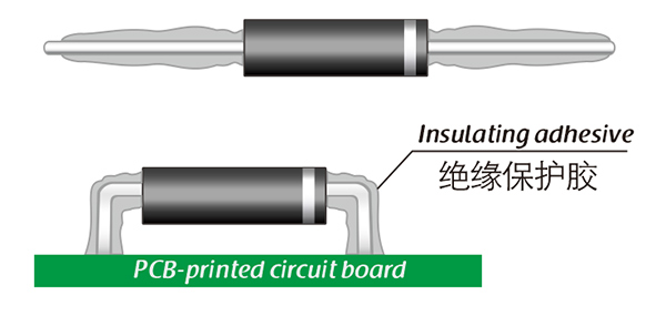
Common treatment methods for surface adhesive insulation:

Characteristics of insulation adhesive material:

1. Silicone material usually presents a transparent and elastic rubber state after curing, which is more effective in shock resistance and can also withstand severe stress changes caused by large high and low temperature changes (-40 ° C~200 ° C).

2. Acrylic materials typically exhibit a transparent and hard coating after curing, with low moisture absorption and fast curing time, as well as excellent wear resistance and insulation.

3. After curing, Urethane material usually presents a transparent and hard coating, which has superior wear resistance and good moisture resistance. Its performance is particularly stable in low temperature environments, but it is less resistant to high temperatures.

4. The coating material based on epoxy is very sturdy and usually opaque, with good moisture and moisture resistance. Its resistance to chemical corrosion and wear is also very good. In addition, epoxy also has good dielectric properties.

Here, suitable insulation adhesive materials can be selected based on the different usage situations of engineers.

HVDIODE - Suly Electronics Co., Ltd.

Expects To Provide You With Perfect Service

Name
Email *
Verification Code *
Click to verify
Leave a message
Name
Email *
Message
Verification Code *
Click to verify
We use Cookie to improve your online experience. By continuing browsing this website, we assume you agree our use of Cookie.