• 2CL2K Power Frequency HV diodes 18KV 200mA 50-60Hz
  • 2CL2K Power Frequency HV diodes 18KV 200mA 50-60Hz
  • 2CL2K Power Frequency HV diodes 18KV 200mA 50-60Hz
  • 2CL2K Power Frequency HV diodes 18KV 200mA 50-60Hz
  • 2CL2K Power Frequency HV diodes 18KV 200mA 50-60Hz
  • 2CL2K Power Frequency HV diodes 18KV 200mA 50-60Hz

2CL2K Power Frequency HV diodes 18KV 200mA 50-60Hz

Products Main features:
1、Axial leaded connection.
2、High thermal conductivity epoxy compound molding.
3、Low internal resistance reduces energy loss.
4、Special passivation glue chip protection
5、Excellent discharge characteristics.
  • 2CL2K Power Frequency HV diodes 18KV 200mA 50-60Hz
  • 2CL2K Power Frequency HV diodes 18KV 200mA 50-60Hz
  • 2CL2K Power Frequency HV diodes 18KV 200mA 50-60Hz
  • Desciption

  • data sheet

  • Installation Guide

Product Overview

This axial-leaded, power-frequency high voltage diode is built for rectification at 50/60 Hz. Read together, those figures describe a part sized for continuous line-frequency rectification inside a high-voltage stack. The people who specify it usually have one of three jobs in front of them: laying out the rectifier stage of a line-frequency high-voltage supply, replacing a failed axial diode in equipment that is already in service, or checking a proposed rating against a printed datasheet before a design review. In all three cases the useful information is the same, and it is the short list that gets compared across high voltage diode manufacturers: blocking voltage, average current, surge capability, temperature window and the shape of the leads. It sits in the 2CL2 series next to a 12 kV version at the same 200 mA rating, so a design that needs less blocking voltage can often keep the rest of its layout unchanged. What the two share is the axial format and the line-frequency intent; what separates them is simply how much reverse voltage each one has to hold.

Construction Features

  • Axial leaded connection. Straight wire leads let the body bridge a point-to-point gap, pass through plated holes or stand in a vertical stack, and they give the body the mechanical support that high voltage diodes in stacked assemblies rely on.
  • High thermal conductivity epoxy compound molding. The encapsulant is chosen to move heat out of the junction rather than hold it in, which matters when the part sits inside a sealed enclosure where the surrounding medium is already warm.
  • Low internal resistance, lower energy loss. A lower forward drop across the 200 mA conduction interval turns less of the throughput into waste heat, so the body runs cooler through long periods of forward conduction.
  • Special passivation glue chip protection. The passivation layer over the chip holds leakage current steady and keeps moisture and contamination away from the junction, which is where high-voltage failures usually begin.
  • Excellent discharge characteristics. The part copes with the steep current step that appears when a charged capacitor bank empties through it, a duty that a steady-state current rating alone does not describe.

Operating Environment & Mounting

  1. Insulating oil. Oil is the recommended medium: it raises the dielectric strength around the body and carries heat away from the epoxy, and it is how most high-voltage rectifier stacks in tanks are built.
  2. Insulating gas. A dry insulating gas atmosphere is also recommended, and it suits assemblies where oil handling or oil weight is a problem. Set the clearances around the leads for the gas you are using rather than for oil.
  3. Secondary encapsulation. Potting the finished assembly places higher demands on the part's heat dissipation and parameter stability, so check that the surrounding compound together with the operating current keeps the body inside its rated ambient.
  4. Open air or forced air cooling. This works, but a high voltage diode of this body size discharges more readily in air and dissipates heat only averagely. Fit insulated electrodes at both ends of the part and add airflow before you push toward the full current rating.
  5. Cleanliness before assembly. Flux, dust and fingerprints on the epoxy give leakage a path across the body, so clean and dry the part before it goes into a high-voltage assembly and handle it by the leads where you can.

Typical Applications

  • Line-frequency rectifier stages in high-voltage DC supplies. The diode blocks the full reverse voltage on one half-cycle and feeds the smoothing network on the other, and its 200 mA average rating sets the usable output current of that stage rather than the peak.
  • Voltage multiplier columns. Ladders that step a modest AC input up to tens of kilovolts string several rectifiers in series; straight axial leads make each stage easy to solder, support and encapsulate.
  • Medical imaging generators. Rectifier sections in X-ray and imaging generator power stages run at line frequency and need a reverse rating that sits comfortably above the rail they feed.
  • Industrial NDT and electrostatic equipment. Non-destructive testing sets, electrostatic generators and high-voltage test gear that rectify at 50/60 Hz and then smooth the result into a high-voltage rail.
  • Repair and replacement. Service teams matching a failed axial diode by reverse voltage, forward current and lead spacing, where the marking on the old body is often the only surviving record of the specification.
  • Series stacks for higher blocking voltage. Where a rail exceeds a single device's rating, several parts are arranged in series so the voltage is shared across the string.

Technical Specifications

ParameterRating
Product model2CL2K
Repetitive peak reverse voltage (Vrrm)18 kV at Ta = 25 °C, Ir = 2.0 µA
Peak working reverse voltage (Vrwm)18 kV at Ta = 25 °C, Ir = 2.0 µA
Average forward current (If(AV))200 mA, 50 Hz half-sine wave, resistive load, break temperature 50 °C
Reverse recovery time (Trr)Not specified for this power-frequency type
Surge forward current (Ifsm)20 A, 0.01 s half-sine wave at 50 Hz
Forward peak voltage (Vfm)≥ 20.0 V
Reverse leakage current at 25 °C (Irrm1)2.0 µA at VRM = VRRM
Reverse leakage current at 100 °C (Irrm2)20.0 µA at VRM = VRRM
Operating ambient temperature (Ta)-55 °C to +150 °C
Storage temperature (Tstg)-55 °C to +125 °C
ConnectionAxial leaded

Surface Insulation Compounds

In a high-voltage build the coating over the body is part of the dielectric design, not a finish. Four families are used, and the right one depends on the medium, the temperature swing and how much mechanical shock the assembly will see.

Silicone compounds cure to a transparent, elastic rubber. They absorb shock and vibration better than the rigid coatings and tolerate the severe stress of large temperature swings from -40 °C to 200 °C, which makes them the usual choice where an assembly cycles hot and cold.

Acrylic compounds cure to a clear, hard coating with low moisture absorption and a fast cure time, plus good wear resistance and dielectric strength — useful when the board or stack has to be handled soon after coating.

Urethane coatings also cure hard and clear. They resist wear strongly and handle moisture well, and they stay stable at low temperature, but they tolerate heat less well than the other three.

Epoxy-based coatings are rigid and usually opaque. They resist moisture, chemical attack and wear, and they have good dielectric properties, which is why they turn up on parts that will be potted or exposed to process chemicals.

Tell us the medium — oil, gas, air or potting compound — and the temperature range the assembly will see, and we will point you to the compound that fits. On high voltage diodes the coating choice changes how leakage behaves over life, so it is worth settling before the build is released.

Ordering & Delivery

  1. Send the circuit details first. Working voltage, average forward current, waveform, cooling medium and mounting style let us check the rating against your design before anything is committed.
  2. Settle quantities and terms with your sales contact. Minimum order quantity, price and current lead time are quoted per order rather than fixed here, so ask for them against your build schedule.
  3. Ask for the paperwork you need. The datasheet and installation guide are available for your files; request the dimension drawing as well if your mechanical layout is already fixed. As high voltage diode manufacturers we can also walk through any figure on the datasheet and send the test data behind it.
  4. Shipping. Shipment is by International express, so give us a delivery address where someone can receive and sign for the parcel.
  5. Plan repeat builds early. If the design is moving from prototype to series production, tell us the forecast with the first order so the same rating can be planned into later releases.

Technical Support & Model Matching

Selection starts with your circuit, not a catalogue number: tell us the working voltage, load current, switching frequency and ambient cooling conditions, and our engineers will match a model from our range and explain the margin left in the design. Each model ships with its datasheet, package drawing and installation guide, and we stay available for mounting and soldering questions, start-up checks and fault finding when an existing part runs hot or fails early. Orders run from about 7 days to 6 months depending on quantity, usually by international express.
FAQ

What is the difference between Vrrm and Vrwm, and why are both 18 kV here?

Vrrm is the repetitive peak reverse voltage the diode is rated to block, and Vrwm is the peak working reverse voltage it can hold in normal operation. On this part both are 18 kV at 25 °C with 2.0 µA of leakage, so there is no lower working ceiling to design around. You can design your reverse voltage directly against the 18 kV figure, with your own additional margin for transients.

There is no recovery time in the datasheet — does the diode still switch?

Reverse recovery time is left blank because this is a 50/60 Hz rectifier; the fast switching that high voltage diodes are chosen for in inverter and pulse circuits is not what this family is optimised for. At line frequency the diode has ample time to recover between half-cycles. If your circuit works at high frequency, a fast-recovery type is the correct choice instead.

What does the 20 A surge rating actually cover?

It is a 0.01 s half-sine surge at 50 Hz — a short overload rather than a continuous current. A high voltage diode that discharges a capacitor bank repeatedly sees many such pulses, so if the application is discharge-heavy, tell us the pulse rate and the energy involved and we will check the margin with you.

Why is the storage temperature range narrower than the operating range?

The diode operates from -55 °C to +150 °C but is rated for storage from -55 °C to +125 °C. Keep spares and buffer stock inside the storage window: a warehouse shelf or a shipping container that sits above 125 °C is outside the specification, even though the part would tolerate that level of heat while it is running.

How do I cross-reference an existing axial diode to this one?

Start with the reverse voltage and the average forward current at your own duty cycle, then check the lead form and body size against the space the old part occupied. A higher Vrrm does not on its own make a part a drop-in replacement, because the body and leads still have to fit. Send the marking on the old body or its datasheet and we will compare it against our range — this is the usual route when a design moves between high voltage diode manufacturers.

Will it work at 60 Hz as well as at 50 Hz?

Yes. The ratings are quoted on a 50 Hz half-sine waveform, and 60 Hz is the same class of line-frequency duty with a slightly shorter period. What matters more is the shape of your waveform and the nature of the load: if the current is not a clean half-sine into a resistive load, ask us to check the margin before you fix the rating in your design.

The selection of high-voltage diodes is closely related to their usage environment。

1. Used in insulating oil. (Recommended)
2. Used in insulating gases. (Recommended)
3. Secondary packaging use. (High requirements for heat dissipation and other parameter performance of components)
4. Use in exposed air or add air cooling. (If the size of the high-voltage diode is small, it is easy to discharge, and the heat dissipation performance is average.)

For high-voltage diodes used in exposed air, it is recommended to install them with insulated electrodes at both ends.


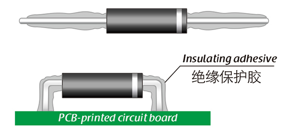
Common treatment methods for surface adhesive insulation:

Characteristics of insulation adhesive material:

1. Silicone material usually presents a transparent and elastic rubber state after curing, which is more effective in shock resistance and can also withstand severe stress changes caused by large high and low temperature changes (-40 ° C~200 ° C).

2. Acrylic materials typically exhibit a transparent and hard coating after curing, with low moisture absorption and fast curing time, as well as excellent wear resistance and insulation.

3. After curing, Urethane material usually presents a transparent and hard coating, which has superior wear resistance and good moisture resistance. Its performance is particularly stable in low temperature environments, but it is less resistant to high temperatures.

4. The coating material based on epoxy is very sturdy and usually opaque, with good moisture and moisture resistance. Its resistance to chemical corrosion and wear is also very good. In addition, epoxy also has good dielectric properties.

Here, suitable insulation adhesive materials can be selected based on the different usage situations of engineers.

HVDIODE - Suly Electronics Co., Ltd.

Expects To Provide You With Perfect Service

Name
Email *
Verification Code *
Click to verify
Leave a message
Name
Email *
Message
Verification Code *
Click to verify
We use Cookie to improve your online experience. By continuing browsing this website, we assume you agree our use of Cookie.