• 2CL2P Power Frequency HV diodes 30KV 150mA 50-60Hz
  • 2CL2P Power Frequency HV diodes 30KV 150mA 50-60Hz
  • 2CL2P Power Frequency HV diodes 30KV 150mA 50-60Hz
  • 2CL2P Power Frequency HV diodes 30KV 150mA 50-60Hz
  • 2CL2P Power Frequency HV diodes 30KV 150mA 50-60Hz
  • 2CL2P Power Frequency HV diodes 30KV 150mA 50-60Hz

2CL2P Power Frequency HV diodes 30KV 150mA 50-60Hz

Products Main features:
1、Axial leaded connection.
2、High thermal conductivity epoxy compound molding.
3、Low internal resistance reduces energy loss.
4、Special passivation glue chip protection
5、Excellent discharge characteristics.
  • 2CL2P Power Frequency HV diodes 30KV 150mA 50-60Hz
  • 2CL2P Power Frequency HV diodes 30KV 150mA 50-60Hz
  • 2CL2P Power Frequency HV diodes 30KV 150mA 50-60Hz
  • Desciption

  • data sheet

  • Installation Guide

Product Overview

The 2CL2P is a power-frequency high voltage diode: it rectifies at 50/60 Hz, the frequency of a mains-driven high voltage supply, rather than switching at kilohertz rates. Its job is to block a large reverse voltage through the non-conducting half cycle and pass a steady forward current through the conducting one. That places the part near the top of the power-frequency range, where one device can do the work of a stack. Physically it is axial leaded: a molded cylindrical body with one lead at each end, sized to sit inside an oil-filled tank, a gas-insulated enclosure or a potted high voltage module. The leads can stay straight for point-to-point wiring or be formed for a board, and the part is normally soldered or held in a clamp inside the rectifier leg. Typical buyers are design engineers specifying the rectifier in a new high voltage supply, buyers re-ordering against a BOM, and repair workshops replacing a failed part in older equipment. As high voltage diode manufacturers we supply this model both for new designs and as a service replacement, and we quote its ratings together with the test conditions they were measured under.

Key Features

  • Axial leaded connection. One lead at each end of a molded body, so the part mounts through a board or between two bus points without a socket or a heatsink bracket; lead length also sets how much of the body sits in cooling oil.
  • High thermal conductivity epoxy compound molding. The chip and its internal connections are encapsulated in an epoxy chosen to carry heat out of the junction, which is what keeps the forward-current capability usable inside a sealed, unventilated tank.
  • Low internal resistance reduces energy loss. Conduction losses stay low at the rated current, so less heat is generated inside the body and the surrounding insulation is not asked to absorb it.
  • Special passivation glue chip protection. The chip surface is passivated and protected before molding, which is what keeps reverse leakage stable and shields the junction from moisture and ionic contamination over a long service life.
  • Excellent discharge characteristics. The part rides out the capacitive inrush and discharge pulses a high voltage supply sees at switch-on, so a short surge does not have to be engineered out with extra series resistance.
  • One construction across the range. Axial leads, epoxy molding and passivated chips carry across our high voltage diodes, so a board that mixes power-frequency and fast-recovery rectifiers needs only one mounting method and one set of assembly rules.

Installation and Operating Environment

  1. Insulating oil — the first choice. Immersing the diode in clean, dry transformer oil carries heat away from the body and suppresses corona at the lead ends, which is where a high voltage rectifier normally breaks down first. Let the part hang clear of the tank wall rather than resting against it.
  2. Insulating gas — the second choice. A gas-filled enclosure works on the same principle, but gas removes heat far less effectively than oil. Check the temperature inside the enclosure and keep the running current comfortably below the rating if it runs warm.
  3. Secondary packaging — potting or encapsulation. Burying the part in a potted module or adding a second insulation layer is workable, but heat then has further to travel. Treat the surrounding compound as part of the thermal design rather than as a cover, and check the component's electrical margin accordingly.
  4. Exposed air — only with forced cooling. In open air a small diode discharges more easily at the lead ends and convection removes very little heat. Add air cooling, keep the assembly clean and dry, and expect less margin than you would have in oil.
  5. Insulated electrodes at both ends. Whenever the part runs in exposed air, fit insulated electrodes at both ends. It is the practical fix for corona and creepage, and it costs far less than finding the fault after the tank is filled.
  6. Mount so the field does not concentrate. Whichever medium you use, keep the body clear of metalwork and avoid a lead end sitting close to a grounded surface — high voltage diodes in oil and in gas both fail where the field concentrates.

Polarity & Fit Check

  • The identifier sits on the body, and the body ends up hidden. Once the part is inside a clamp, a holder sleeve or a potted block, the marking that shows which end is the cathode is out of sight. Settle the orientation before the part goes in, not afterwards. - Mark the cathode lead before you trim or form it. A short piece of heat-shrink sleeving in a contrasting colour, or a flag of tape on that lead, keeps the direction readable through assembly and final inspection. - Diode-test the part before it disappears into the tank. On a multimeter's diode range you should read forward one way and open circuit the other. It takes a moment and catches a wrong-way part while the assembly is still on the bench. - A reversed leg runs hot and rectifies nothing. The output shows the reverse half cycle, ripple appears at line frequency, and the diode warms up without doing useful work — anything downstream then sees alternating voltage instead of DC. - Follow the direction along a whole series string. Where several elements are stacked, every one must point the same way along the string; a single reversed element blocks the leg. Lay the string out on the bench in final order and trace the bands from end to end before soldering. - Measure your cavity before you order, not after delivery. Check the holder recess or the board footprint against three things: body diameter and body length, lead diameter versus the hole or terminal size, and the lead spacing you will have once the leads are formed. A part resting against a surface is a future flashover point. If the space is tight, tell us the room you have and we will confirm which model in the range will sit in it.

Soldering & Lead Forming

  1. Put the heat on the lead, not the molding. Use a temperature-controlled iron set just high enough to wet the joint quickly, and keep the tip on the lead where it leaves the body. The epoxy takes a brief touch; it will not take a hot iron resting against it, and a softened seal is where tracking begins years later.
  2. Clip a heat sink between the joint and the body. A small aluminium clip or a pair of forceps on the lead, close to the molding, carries heat away during a longer joint. It costs seconds and protects a part that will spend its service life holding off 30 kV.
  3. Form the lead once, with support. Grip the lead on the body side of the bend with flat pliers and bend only the free length, giving the corner a radius rather than a crease. Plating cracks at a sharp bend, and a lead rocked back and forth can open the seal where it leaves the epoxy.
  4. Trim after forming, not before. Cut with sharp side cutters and keep the cut clean — a nicked lead is a stress riser that fails in service. Leave enough length that the joint or clamp sits clear of the body.
  5. Choose solder or a clamp to suit the assembly. Solder for a permanent connection on a wired or board assembly; use a screw clamp or terminal block where the lead must stay long and the part may be serviced. Re-check clamp torque after the first thermal cycle.
  6. Clean the flux and let it dry. Brush the joint area with isopropyl alcohol and let it evaporate completely before potting or immersion. Keep solvent off the printed marking, which an aggressive cleaner can soften.
  7. Support the body, not only the leads. In an oil tank or a potted block, hold the diode so its weight and any vibration are not carried by the solder joints; a small bracket or the surrounding compound does that job.
  8. Do not send it through reflow. This is a through-hole, axial-leaded high voltage diode, intended for hand soldering or clamping rather than a reflow oven or wave solder bath. If a lead has been bent and straightened more than once, treat the part as a replacement candidate rather than trusting it at a high-voltage node.

Typical Applications

Anything that steps mains up through a transformer at 50/60 Hz and then rectifies it is a candidate. DC high voltage generators and HVDC supplies are the plainest case: the transformer secondary feeds one or more rectifier legs, the diode holds off the peak secondary voltage, and the output charges a smoothing capacitor.

Hipot and dielectric test sets, high voltage test transformers and test benches work the same way, with the rectifier charging the output capacitor up to the test voltage. Currents there are modest and steady, which is exactly the duty a power-frequency part is rated for.

Imaging equipment is the other large group — X-ray generator tanks, DR and CT high voltage sections, portable dental panoramic heads and electron accelerator supplies. In most of these the rectifier sits in oil, so its behaviour at tank temperature and its compatibility with the insulating medium matter as much as the blocking voltage.

Industrial non-destructive testing adds a more portable version of the same circuit: X-ray inspection of welds, castings and pipelines, where the oil volume is smaller and the cooling margin thinner.

Radar and accelerator power supplies, and laboratory high voltage rigs built at universities and research institutes, round out the list. When you are comparing high voltage diodes across families, the deciding question is simply whether the circuit runs at line frequency — if it does, this is the right family to be in.

Data Sheet Ratings

ParameterSymbolTest conditionsValue
Repetitive peak backward voltageVrrmTa = 25 °C, Ir = 2.0 µA30 kV
Peak working backward voltageVrwmTa = 25 °C, Ir = 2.0 µA30 kV
Average forward currentIf(AV)50 Hz half-sine, resistive load, Tbreak = 50 °C150 mA
Backward recovery timeTrrNot applicable to this power-frequency part—
Surge forward currentIfsm0.01 s, half-sine, 50 Hz15 A
Forward peak voltageVfm—≥35.0 V
Backward peak currentIrrm1Ta = 25 °C, VRM = VRRM2.0 µA
Backward peak currentIrrm2Ta = 100 °C, VRM = VRRM20.0 µA
Operating ambient temperatureTa—-55 to +150 °C
Storage temperatureTstg—-55 to +125 °C

Voltage Class Selection

  • Two jobs, one series. The 2CL2R is the higher-voltage member at 35 kV; this model sits below it and answers with current instead. Read your stack voltage first and your load current second, and the choice usually makes itself.
  • What you gain by stepping down. Giving up 5 kV of blocking voltage buys a clearly higher average forward current and a surge rating half again as large — worth having in a capacitive load, where the switch-on pulse rather than the steady current is what stresses the rectifier.
  • What you should not give up. If transients in your circuit approach the top of the reverse range, or if the equipment has to pass a flashover test above it, stay with the 35 kV part. Blocking margin is the last thing to trim in a high voltage diode that has to hold off a fault.
  • Forward drop follows the voltage class. The lower-voltage part also has the lower forward peak voltage, so conduction loss at a given current is smaller — a small gain per device that adds up when several rectifier legs run at once.
  • Cross-referencing a failed part. A rectifier marked 2CL2R in equipment that runs well inside 30 kV can be replaced with this model when more current is wanted; going the other way, from this part up to the 35 kV version, costs current capability rather than adding it.

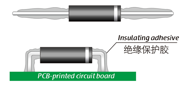
Insulation Adhesive Options

  • Silicone — the shock absorber. Cures to a transparent, elastic rubber with the widest temperature range of the four, roughly -40 °C to +200 °C, and copes with severe swings between hot and cold. Choose it where mechanical shock and thermal expansion are the main threat and a compliant surface is acceptable.
  • Acrylic — fast and hard. Cures quickly to a transparent, hard coating with low moisture absorption, good wear resistance and good insulation. It suits volume assembly where curing time matters and the part will not see repeated mechanical stress.
  • Urethane — cold-weather stability. Also cures hard and transparent, with strong wear resistance and good moisture resistance; its performance holds particularly well at low temperature, while its high-temperature resistance is weaker than silicone's. A reasonable choice for equipment that runs cold and wet rather than hot.
  • Epoxy — the sealed, rugged option. A very sturdy coating, usually opaque, with good resistance to moisture, chemical attack and wear, plus good dielectric properties. Use it where the environment is aggressive and the part does not need to be inspected afterwards.
  • Match the compound to the medium. The adhesive is not only electrical insulation: it is also the thermal path between the body and whatever surrounds it, and the mechanical bond that stops the part moving inside a tank. Tell us the medium, the ambient temperature and any cleaning chemicals used at the site, and choose against those three rather than by habit.

Ordering and Delivery

  • Tell us the duty, not just the part number. Reverse voltage, load current, operating frequency and the cooling medium are enough for us to confirm that this model is the right fit rather than the nearest fit. As high voltage diode manufacturers we would rather check those four figures against the ratings than have you find out later that the next step in the series was the better match.
  • Quantity and packing. Tell us the quantity for the first order and whether the parts must arrive in a particular packing format for your line; packing is confirmed with the quotation.
  • Lead time and payment terms. Both are quoted per order and vary with quantity and destination, so confirm them with your sales contact when you place the enquiry.
  • Shipping. Orders ship by international express.
  • Documentation. The data sheet and installation guide for the model supplied travel with the order; ask for a dimension drawing with your enquiry if you need to check body and lead dimensions against a holder or a board.
  • Before and after the sale. Send mounting, soldering and start-up questions to the same contact who handled the order. A rectifier that runs hot or fails early is usually a mounting or medium problem, and it is much faster to diagnose with the drawing and the test conditions in hand.

Technical Support & Model Matching

Selection starts with your circuit, not a catalogue number: tell us the working voltage, load current, switching frequency and ambient cooling conditions, and our engineers will match a model from our range and explain the margin left in the design. Each model ships with its datasheet, package drawing and installation guide, and we stay available for mounting and soldering questions, start-up checks and fault finding when an existing part runs hot or fails early. Orders run from about 7 days to 6 months depending on quantity, usually by international express.
FAQ

Why is there no backward recovery time figure for this diode?

Recovery time describes how quickly a diode stops conducting when it is switched off, and it only becomes a design constraint once the circuit switches at kilohertz rates — a switching supply, an inverter or a pulse generator. In a 50/60 Hz rectifier the diode turns off with the mains waveform, so the parameter has no meaning for the application. If your circuit does switch fast, tell us the switching frequency and we will point you to a fast-recovery part in the range instead.

Which end is the cathode, and how should the part be oriented?

The banded end of the body is the cathode. Fit it so the cathode faces the more positive side of the circuit — in a rectifier leg that means towards the DC output. Reversed, the diode will not rectify: the supply will show the reverse half cycle at the output and the part will run hot even though it is not necessarily damaged. If the band will end up hidden inside a clamp or a potted assembly, mark the lead before you form or cut it.

Can I solder this part, and how should the leads be bent?

Both soldering and clamping are normal. Solder quickly and keep the heat on the lead rather than the body; a small heat-sink clip on the lead between the joint and the molding is inexpensive insurance. When forming a lead, support it on the body side of the bend and give it a radius rather than a sharp crease — repeated tight bends crack the plating, and a lead worked back and forth can open the seal where it leaves the molding.

Can one 30 kV diode replace a series string of smaller diodes?

For power-frequency work, usually yes, and it makes a simpler assembly. A string of lower-voltage high voltage diodes has to be arranged so the reverse voltage divides evenly between the elements, and every extra joint is a place for corona to start. One 30 kV part removes both problems, along with the soldering that went with them. What you give up is field repairability — a string can be rebuilt one element at a time, while a single device is replaced whole — so weigh that if the equipment is serviced on site.

Which temperature range applies in storage, and which in service?

The data sheet gives two separate ranges and they are not interchangeable. The operating ambient range covers a powered part working in its tank, enclosure or cabinet; the storage range covers an unpowered part in a store, in transit or waiting on a shelf, and its upper limit is the lower of the two. Plan spares and stock against the storage range and the working environment against the operating range. If a process step — curing, potting, a drying oven — will take the part above the storage ceiling before it is ever powered, confirm that with us first rather than assuming the operating figure covers it.

The selection of high-voltage diodes is closely related to their usage environment。

1. Used in insulating oil. (Recommended)
2. Used in insulating gases. (Recommended)
3. Secondary packaging use. (High requirements for heat dissipation and other parameter performance of components)
4. Use in exposed air or add air cooling. (If the size of the high-voltage diode is small, it is easy to discharge, and the heat dissipation performance is average.)

For high-voltage diodes used in exposed air, it is recommended to install them with insulated electrodes at both ends.


Common treatment methods for surface adhesive insulation:

Characteristics of insulation adhesive material:

1. Silicone material usually presents a transparent and elastic rubber state after curing, which is more effective in shock resistance and can also withstand severe stress changes caused by large high and low temperature changes (-40 ° C~200 ° C).

2. Acrylic materials typically exhibit a transparent and hard coating after curing, with low moisture absorption and fast curing time, as well as excellent wear resistance and insulation.

3. After curing, Urethane material usually presents a transparent and hard coating, which has superior wear resistance and good moisture resistance. Its performance is particularly stable in low temperature environments, but it is less resistant to high temperatures.

4. The coating material based on epoxy is very sturdy and usually opaque, with good moisture and moisture resistance. Its resistance to chemical corrosion and wear is also very good. In addition, epoxy also has good dielectric properties.

Here, suitable insulation adhesive materials can be selected based on the different usage situations of engineers.

HVDIODE - Suly Electronics Co., Ltd.

Expects To Provide You With Perfect Service

Name
Email *
Verification Code *
Click to verify
Leave a message
Name
Email *
Message
Verification Code *
Click to verify
We use Cookie to improve your online experience. By continuing browsing this website, we assume you agree our use of Cookie.