• 2CL2R Power Frequency HV diodes 35KV 100mA 50-60Hz
  • 2CL2R Power Frequency HV diodes 35KV 100mA 50-60Hz
  • 2CL2R Power Frequency HV diodes 35KV 100mA 50-60Hz
  • 2CL2R Power Frequency HV diodes 35KV 100mA 50-60Hz
  • 2CL2R Power Frequency HV diodes 35KV 100mA 50-60Hz
  • 2CL2R Power Frequency HV diodes 35KV 100mA 50-60Hz

2CL2R Power Frequency HV diodes 35KV 100mA 50-60Hz

Products Main features:
1、Axial leaded connection.
2、High thermal conductivity epoxy compound molding.
3、Low internal resistance reduces energy loss.
4、Special passivation glue chip protection
5、Excellent discharge characteristics.
  • 2CL2R Power Frequency HV diodes 35KV 100mA 50-60Hz
  • 2CL2R Power Frequency HV diodes 35KV 100mA 50-60Hz
  • 2CL2R Power Frequency HV diodes 35KV 100mA 50-60Hz
  • Desciption

  • data sheet

  • Installation Guide

Rectification Duty

A power-frequency rectifier is designed around a different constraint from a fast-recovery part, and the missing recovery-time figure says so. At 50 or 60 Hz each half-cycle lasts between eight and ten milliseconds; the charge stored in the junction clears in a time so short against that window that it has no bearing on loss, heating or EMI. Putting die area into a fast-recovery structure would add cost without changing anything the circuit sees. Where the design does run at switching frequencies, or fires in short pulses, this is the wrong family and the fast-recovery parts are the ones to look at.

What limits this part instead is forward drop and heat. The forward peak voltage is at least 42 V, and a conducting device at 100 mA turns that into continuous dissipation inside a small epoxy body, which is why the molding compound's thermal conductivity and the surrounding insulation both count as part of the design. The same part sitting in oil sheds heat very differently from one standing in air.

The 35 kV figure appears twice, as repetitive peak reverse voltage and as peak working reverse voltage, so there is no hidden gap between the two names; both are quoted at 25 °C with 2.0 µA of reverse current. Current is specified as 100 mA average under a 50 Hz half-sine wave into a resistive load at a 50 °C break temperature — a defined operating point rather than an open-ended maximum, so a hotter case or a harsher waveform needs margin above it rather than the figure taken at face value.

If your circuit needs more current rather than more blocking voltage, the 30 kV / 150 mA part in the same family carries 15 A of surge instead of 10 A. If the rail only reaches a few kilovolts, a smaller fast-recovery diode will do the job with less bulk.

Product Overview

The 2CL2R is an axial-leaded, epoxy-molded high voltage diode built for one job: rectifying a high voltage rail that starts at a mains transformer. Its ratings are 35 kV repetitive peak reverse voltage and 100 mA average forward current at 50/60 Hz, placing it at the top of the voltage range in our power-frequency family.

Circuits of that shape turn up wherever DC is derived from an AC high voltage source — DC high voltage generators, hipot and insulation test sets, high voltage test transformers and the rectifier chains inside X-ray generator tanks. The diode blocks the reverse half-cycle, conducts the forward half-cycle into the smoothing capacitor or the next stage of a multiplier, and repeats the sequence at line frequency with no recovery penalty to design around.

The body is a black epoxy cylinder with a silver cathode band at one end and two metallic axial leads. The leads can be formed to reach a board, a bracket or a terminal, which is what makes the part usable both in new assemblies and in repair work on existing stacks.

Each rating is quoted together with the condition it was measured under, so the incumbent part in your stack can be compared with this one figure by figure rather than by headline voltage.

Key Features

  • Axial leaded connection. The through-hole axial format drops into existing stacks, brackets and hand-soldered assemblies without a board redesign, and it is just as comfortable in wave-soldered production. - High thermal conductivity epoxy molding. Heat leaves the die through the molding compound instead of sitting at the junction, which is what keeps a continuous 100 mA conduction duty stable over a long run. Every part in our axial high voltage diodes range is built the same way. - Low internal resistance. Conduction loss at the rated current stays low, so a device buried in a series string does not add avoidable heat to the assembly. - Special passivation glue chip protection. The chip surface is sealed before molding, holding back the moisture and ionic contamination that push reverse leakage upward in high voltage parts.

Mounting & Insulation

  1. Choose the insulation environment before the assembly layout is fixed. Immersion in insulating oil is the recommended route at this voltage, with insulating gas the second choice; both control the field around the leads far better than open air.
  2. If the diode lives inside a secondary package or a sealed module, treat the enclosure as part of the thermal design — a closed volume decides how much heat can leave the body, and the parameter margins shrink with it.
  3. For exposed-air mounting, add air cooling where you can and keep other metalwork out of the immediate field. A body this small discharges easily across a short path in air.
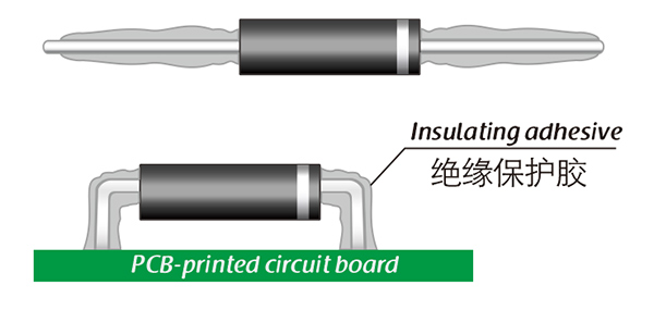
  4. Fit insulated electrodes at both ends when the part runs in air. The lead exits are where the field concentrates on high voltage diodes of this size, and insulating the ends is the simplest way to stop surface tracking.
  5. Form and bend the leads before soldering, then clean the body and the lead exits before coating. Adhesive applied over flux residue traps contamination against the surface.
  6. Apply the insulating adhesive in a continuous layer around the lead bend and the body end, with no voids or thin spots; that layer carries as much of the shock and tracking duty as the molding does.
  7. Re-check the finished assembly at working voltage once the coating has cured. A leakage or partial-discharge check at that stage finds voids while the assembly can still be reworked.

Series Stacking & Cathode Orientation

  1. Identify the cathode from the band. The silver band around one end of the black epoxy body marks the cathode, so the lead at that end is the cathode and the plain end is the anode. In a half-wave rectifier the banded end points toward the smoothing capacitor or the load, with the anode toward the transformer secondary.
  2. Record the orientation before desoldering. Photograph the existing stack or mark the band position on the bracket first; once the insulating adhesive is applied the band is buried, and the only remaining record of polarity is your own note.
  3. Bench-check with a source above the forward drop. Forward peak voltage on this high voltage diode is ≥ 42.0 V, so an ordinary multimeter diode test will not turn it on and can read open on a sound part. Use a supply above that figure with a series resistor to limit current, and confirm conduction in one direction only.
  4. Build the string cathode to anode. Above 35 kV, connect two or more devices in series, each anode joined to the next cathode, so every device blocks its own share of the reverse voltage while the forward current passes through the whole chain.
  5. Match the devices before you stack them. Reverse leakage runs 2.0 µA at 25 °C and 20.0 µA at 100 °C, and the device with the lowest leakage at a given temperature carries the largest share of the voltage. Keep one string to a single type and, where possible, a single production lot; do not mix a 2CL2R with another voltage class or with a fast-recovery part.
  6. Grade the DC share with resistors and the fast fronts with capacitors. A resistor across each diode, sized so its current dominates the 20.0 µA worst-case leakage at 100 °C, holds the DC sharing steady as the parts warm and drift apart. Uneven fast transients are a separate problem, carried by capacitance rather than leakage, so a capacitor across each device evens the front as well.
  7. Run each device below its rating. A stack of two 35 kV parts is not a 70 kV rectifier with no margin; keep the per-device working voltage clearly under 35 kV so that imbalance, temperature rise and any single weak device still leave headroom. Oil or gas insulation around the finished string is what makes that margin usable.
  8. Confirm every band faces the same way before coating, then recheck at working voltage after cure. A diode fitted the wrong way round in a series string blocks in the conducting direction, heats and fails, and it is the one mistake a coating hides permanently.

Specifications

ParameterValue and test condition
Repetitive peak backward voltage, Vrrm35 kV at Ta = 25 °C, Ir = 2.0 µA
Peak working backward voltage, Vrwm35 kV at Ta = 25 °C, Ir = 2.0 µA
Average forward current, If(AV)100 mA, 50 Hz half-sine wave, resistive load, Tbreak = 50 °C
Backward recovery time, TrrNot specified — power-frequency rectification
Surge forward current, Ifsm10 A, 0.01 s, 50 Hz half-sine wave
Forward peak voltage, Vfm≥ 42.0 V
Backward peak current, Irrm12.0 µA at Ta = 25 °C, VRM = VRRM
Backward peak current, Irrm220.0 µA at Ta = 100 °C, VRM = VRRM
Operating ambient temperature, Ta−55 to +150 °C
Storage temperature, Tstg−55 to +125 °C
ConstructionAxial leaded, epoxy molded, passivation-protected chip

Insulating Adhesives

  • Silicone. Cures to a transparent, elastic rubber that absorbs mechanical shock and rides out severe hot–cold cycling from −40 °C to 200 °C. The safe default when the assembly will see temperature swings or vibration.
  • Acrylic. Cures to a transparent, hard coating with low moisture absorption and a fast cure time, plus good wear resistance and insulation. Useful when the assembly has to be handled soon after coating.
  • Urethane. Cures transparent and hard, with superior wear resistance and good moisture resistance; it stays stable in low-temperature service but is the weaker choice when the part runs hot.
  • Epoxy. Cures very hard and is usually opaque. Strong against moisture, chemical attack and wear, with good dielectric properties — the choice when the coating also has to protect the body mechanically.
  • Match the material to the environment. Oil immersion, a sealed module and an air-cooled open mount each ask something different of the layer, and the layer is also what keeps surface leakage on a high voltage diode from creeping up in a damp enclosure.

Ordering & Delivery

  1. Send the working voltage, the average and surge current, the operating frequency and the insulation environment the diode will sit in.
  2. Add the marking of any part you are replacing if you want the cross-reference confirmed before committing to a quantity.
  3. Ask your sales contact about sample availability for an evaluation build, and about the quantity you need for production.
  4. Confirm lead time, packing, payment terms and Incoterms with your sales contact when the order is placed.
  5. Shipments go by international express, so plan the receiving end for a parcel rather than a pallet.
  6. As high voltage diode manufacturers we answer rating, mounting and coating questions from the same contact who handles the order.

Technical Support & Model Matching

Selection starts with your circuit, not a catalogue number: tell us the working voltage, load current, switching frequency and ambient cooling conditions, and our engineers will match a model from our range and explain the margin left in the design. Each model ships with its datasheet, package drawing and installation guide, and we stay available for mounting and soldering questions, start-up checks and fault finding when an existing part runs hot or fails early. Orders run from about 7 days to 6 months depending on quantity, usually by international express.
FAQ

What does the ≥42.0 V forward peak voltage mean for my design?

Budget for it. Every conducting device in the string drops at least 42 V, and at the full 100 mA that drop turns into continuous heat inside the epoxy body. In a series stack or a multiplier the individual drops add up, so the DC output is always lower than the transformer secondary suggests and the thermal design has to carry the total. Treat 42.0 V as the ceiling when you size the string and check the real drop at your own current and temperature.

Can I put several in series to block more than 35 kV?

Series strings are the usual route past a single device's rating, and the axial package suits that kind of assembly. Two things decide how well it works. Keep the devices to one type so the leakage spread stays narrow, and remember that leakage climbs from 2.0 µA at 25 °C to 20.0 µA at 100 °C — unequal leakage is what pushes one diode in a string above its share of the voltage. Oil or gas insulation plus a grading network across the string keeps the sharing predictable.

Can you cross-reference the number printed on my old diode?

Send the marking on the old part, the working voltage and a note on how it is mounted. As high voltage diode manufacturers we can usually name the nearest equivalent in our range in a single exchange, because most of these replacements come down to confirming the voltage class and the lead form rather than redesigning the assembly.

Does reverse leakage matter once the equipment is at operating temperature?

It is the figure most likely to catch out a high voltage diode in service. Leakage is 2.0 µA at 25 °C and 20.0 µA at 100 °C at the rated reverse voltage — a tenfold rise. In a measuring instrument that leakage loads the supply and shifts the reading; in a series string it unbalances the voltage sharing. If the assembly runs hot, design the thermal path around the 100 °C figure rather than the room-temperature one.

How do I check it will sit where the old part sat?

Compare body diameter and lead length on the package drawing with the part you are removing, and check how the old leads were dressed — an axial body can be formed to reach a board or a bracket, but the bend has to leave room for the coating. Orientation matters too: the silver band marks the cathode, so fit the banded end the same way as the original and mark its position before the coating goes on. A photo of the old mounting is usually enough for us to confirm the match.

The selection of high-voltage diodes is closely related to their usage environment。

1. Used in insulating oil. (Recommended)
2. Used in insulating gases. (Recommended)
3. Secondary packaging use. (High requirements for heat dissipation and other parameter performance of components)
4. Use in exposed air or add air cooling. (If the size of the high-voltage diode is small, it is easy to discharge, and the heat dissipation performance is average.)

For high-voltage diodes used in exposed air, it is recommended to install them with insulated electrodes at both ends.


Common treatment methods for surface adhesive insulation:

Characteristics of insulation adhesive material:

1. Silicone material usually presents a transparent and elastic rubber state after curing, which is more effective in shock resistance and can also withstand severe stress changes caused by large high and low temperature changes (-40 ° C~200 ° C).

2. Acrylic materials typically exhibit a transparent and hard coating after curing, with low moisture absorption and fast curing time, as well as excellent wear resistance and insulation.

3. After curing, Urethane material usually presents a transparent and hard coating, which has superior wear resistance and good moisture resistance. Its performance is particularly stable in low temperature environments, but it is less resistant to high temperatures.

4. The coating material based on epoxy is very sturdy and usually opaque, with good moisture and moisture resistance. Its resistance to chemical corrosion and wear is also very good. In addition, epoxy also has good dielectric properties.

Here, suitable insulation adhesive materials can be selected based on the different usage situations of engineers.

HVDIODE - Suly Electronics Co., Ltd.

Expects To Provide You With Perfect Service

Name
Email *
Verification Code *
Click to verify
Leave a message
Name
Email *
Message
Verification Code *
Click to verify
We use Cookie to improve your online experience. By continuing browsing this website, we assume you agree our use of Cookie.