The 4 kV step of our axial fast-recovery range, this high voltage diode is a small epoxy-molded cylinder with a straight lead at each end and a band marking the cathode. The chip inside is passivated and encapsulated in a thermally conductive compound, so the part blocks 4 kV of repetitive reverse voltage, carries 5 mA of average forward current and clears its junction in 80 nS. That combination makes it the natural choice when a rectifier string or a multiplier stage needs kilovolts of blocking capability but the stack voltage sits comfortably below the higher steps in the same series.
Four kilovolts is a design point, not a compromise. In a series-stacked rectifier column or in the lower stages of a multiplier, the reverse voltage across each device is fixed by the stack design; a part rated at 6 kV or 8 kV adds no margin unless something in the circuit can actually generate those extra volts, and it brings a higher forward drop with it. This version carries the lowest forward peak voltage of the three axial fast-recovery steps, which matters when 5 mA flows through a string continuously inside a sealed tank: every volt of forward drop is heat you have to get out of the oil. When engineers compare high voltage diode manufacturers, the figures that separate one offer from another are the forward drop at working current, the leakage at 100 °C and whether a recovery time is published at all — all three are stated with their conditions on this product. Stacking is the other question. Several 4 kV parts in series hold off a multiple of 4 kV only if the reverse voltage divides evenly between them, so use sharing resistors or a graded stack design, keep the physical spacing identical from device to device, and confirm the arrangement before you pot it. If the stack still leaves more than one device's rating across each part after your derating factor, move up to the 6 kV or 8 kV member of the same series — the current rating, the recovery time and the axial footprint stay the same, so the board and the potting do not change.
| Part number | 2CL69 |
| Device type | Axial-leaded fast-recovery rectifier diode |
| Repetitive peak reverse voltage (Vrrm) | 4 kV at Ta = 25 °C, Ir = 2.0 µA |
| Peak working reverse voltage (Vrwm) | 4 kV at Ta = 25 °C, Ir = 2.0 µA |
| Average forward current (If(AV)) | 5 mA, 50 Hz half-sine wave, resistive load, Tbreak = 50 °C |
| Reverse recovery time (Trr) | 80 nS |
| Surge forward current (Ifsm) | 0.5 A, 0.01 s half-sine wave at 50 Hz |
| Forward peak voltage (Vfm) | ≥16.0 V |
| Reverse leakage (Irrm1) | 2.0 µA at Ta = 25 °C, VRM = VRRM |
| Reverse leakage (Irrm2) | 20.0 µA at Ta = 100 °C, VRM = VRRM |
| Operating ambient temperature (Ta) | -55 °C to +150 °C |
| Storage temperature (Tstg) | -55 °C to +125 °C |
| Polarity | Cathode band at one end of the body |
| Silicone — cured state | Transparent, elastic rubber |
| Silicone — strengths | Absorbs shock and large temperature swings, roughly -40 °C to +200 °C |
| Acrylic — cured state | Transparent, hard coating |
| Acrylic — strengths | Low moisture absorption, fast cure, high wear resistance and good insulation |
| Urethane — cured state | Transparent, hard coating |
| Urethane — strengths | Very good wear resistance and good moisture resistance; stable at low temperature but less tolerant of high temperature |
| Epoxy — cured state | Usually opaque and very hard |
| Epoxy — strengths | Good moisture, chemical and wear resistance, with good dielectric properties |
Selection starts with your circuit, not a catalogue number: tell us the working voltage, load current, switching frequency and ambient cooling conditions, and our engineers will match a model from our range and explain the margin left in the design. Each model ships with its datasheet, package drawing and installation guide, and we stay available for mounting and soldering questions, start-up checks and fault finding when an existing part runs hot or fails early. Orders run from about 7 days to 6 months depending on quantity, usually by international express.
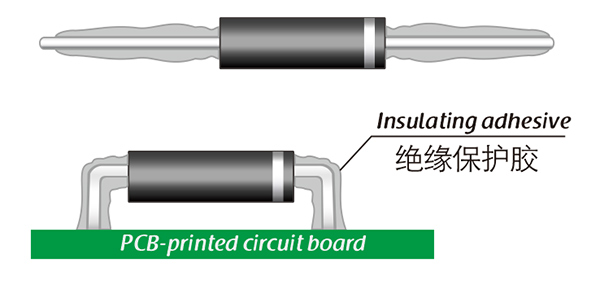
Here, suitable insulation adhesive materials can be selected based on the different usage situations of engineers.