The 2CL77 is a fast recovery high voltage diode rated 20KV, and it holds the middle of the 2CL7 axial range. Its 5mA average forward current, 80nS recovery time and 0.5A surge rating are shared with the 16KV, 18KV and 30KV parts, so the four models differ in blocking voltage and in little else. Between 18KV and 20KV even the forward peak stays at ≥43.0V, which makes the extra two kilovolts a margin that costs nothing in conduction loss. Both blocking figures, repetitive peak and working peak, are quoted at 20KV with 2.0µA of reverse current flowing at 25 °C. Tying a rating to a leakage condition is what makes it usable in a design: the part is expected to hold the full 20KV in service, not only for an instant. The body is a moulded epoxy cylinder with two axial leads and a band at the cathode. It solders into a board, wires point to point into a multiplier ladder, or sits in an oil-filled or potted shell, and the leads form to the hole pitch without special tooling. Every step of the ladder is published by HVDIODE, Suly Electronics Co., Ltd., with its own rating table, test conditions and dimension drawing, in one table format from 16KV to 30KV — the property that lets the figures line up when high voltage diode manufacturers are put side by side. Step | Blocking voltage (Vrrm = Vrwm) | Forward peak voltage | What changes against the step below --- | --- | --- | --- 2CL75 | 16KV | ≥41.0V | Smallest blocking class in the family 2CL76 | 18KV | ≥43.0V | 2KV more blocking, 2V more forward drop 2CL77 | 20KV | ≥43.0V | 2KV more blocking, no change in forward drop 2CL82 | 30KV | ≥52.0V | 10KV more blocking, 9V more forward drop
Imaging power supplies are the usual home for this voltage class. X-ray, DR, CT and dental panoramic generators rectify at high potential inside multiplier stages, and 20KV covers the intermediate stages of those stacks. Industrial high-voltage test and inspection equipment — NDT sets, DC high-voltage generators, HV test transformers — runs at currents the 5mA rating covers, and accelerator and radar supplies use series strings where a defined reverse margin at modest current counts for more than forward capability. Repair and maintenance is the other steady use. Where a stack has failed, the number on the old part is the place to start; the rest of the ladder shares the current, recovery and surge behaviour, so high voltage diodes one step either side of the original are a workable substitution once the reverse margin in the stack has been checked. Prototype and pre-production builds suit the axial format as well, because the leads are hand-solderable and a first article can be assembled without a reflow profile.
The 5mA figure is an average forward current at 50Hz half-sine into a resistive load with Tbreak at 50 °C, and it is the continuous ceiling for this package. It fits the high-voltage side of a supply, where each diode in a multiplier carries only the stage current, but it does not fit a main power path: a design that needs hundreds of milliamps at a few kilovolts belongs in the SMD 5KV range, where a single footprint covers 100mA to 900mA at 75nS.
The other edge is voltage. The ladder stops at 30KV, so a stack that needs more reverse blocking gets more diodes in series rather than a different model, and the forward drops then add along the string.
| Parameter (symbol) | Rating and test condition |
| Repetitive peak reverse voltage (Vrrm) | 20KV at Ta = 25 °C, Ir = 2.0µA |
| Peak working reverse voltage (Vrwm) | 20KV at Ta = 25 °C, Ir = 2.0µA |
| Average forward current (If(AV)) | 5mA, 50Hz half-sine, resistive load, Tbreak = 50 °C |
| Recovery time (Trr) | 80nS |
| Surge forward current (Ifsm) | 0.5A, 0.01s half-sine, 50Hz |
| Forward peak voltage (Vfm) | ≥43.0V |
| Reverse leakage at 25 °C (Irrm1) | 2.0µA at VRM = VRRM |
| Reverse leakage at 100 °C (Irrm2) | 20.0µA at VRM = VRRM |
| Operating ambient temperature (Ta) | -55 to +150 °C |
| Storage temperature (Tstg) | -55 to +125 °C |
| Material | Cured state | Where it suits |
| Silicone | Transparent, elastic rubber | Stacks that see shock and wide temperature swings, roughly -40 °C to +200 °C |
| Acrylic | Transparent, hard coating | Fast-curing coverage where moisture absorption stays low and the coating resists wear |
| Urethane | Transparent, hard coating | Low-temperature assemblies needing wear and moisture resistance, least tolerant of sustained heat |
| Epoxy | Opaque, very rigid | Chemical, moisture and wear exposure where dielectric strength matters most, and the hardest to rework |
The same build is available at 16KV, 18KV and 30KV, so a change of margin mid-project does not change the package or the datasheet layout. The rating table and the dimension drawing go with the order. Delivery is by International express.
Selection starts with your circuit, not a catalogue number: tell us the working voltage, load current, switching frequency and ambient cooling conditions, and our engineers will match a model from our range and explain the margin left in the design. Each model ships with its datasheet, package drawing and installation guide, and we stay available for mounting and soldering questions, start-up checks and fault finding when an existing part runs hot or fails early. Orders run from about 7 days to 6 months depending on quantity, usually by international express.
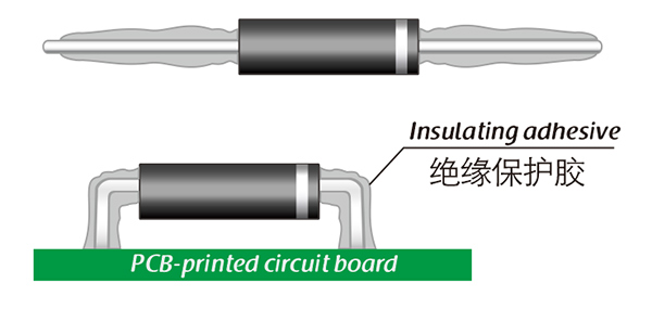
Here, suitable insulation adhesive materials can be selected based on the different usage situations of engineers.