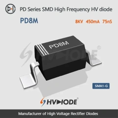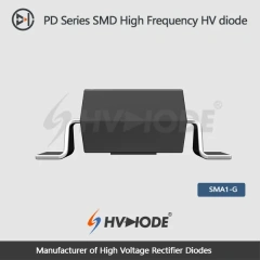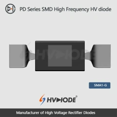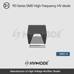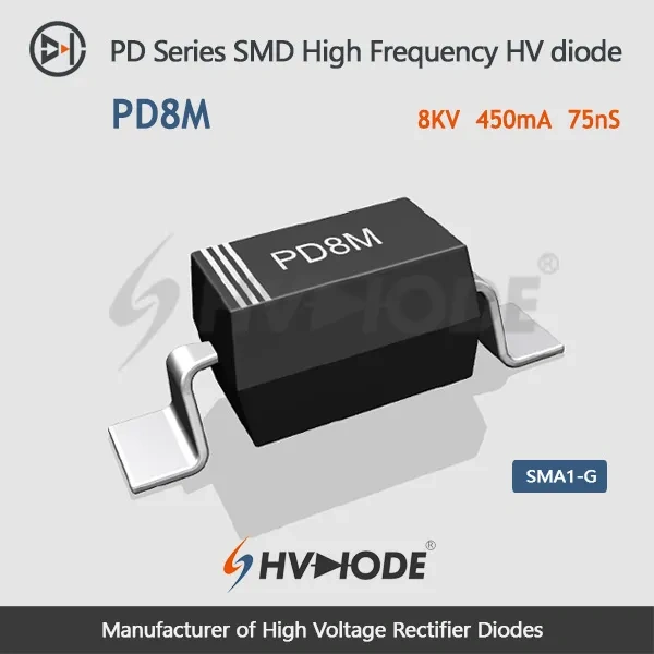
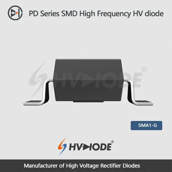
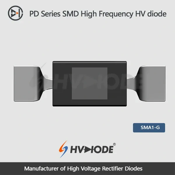
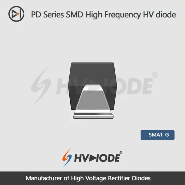
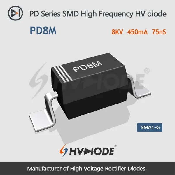
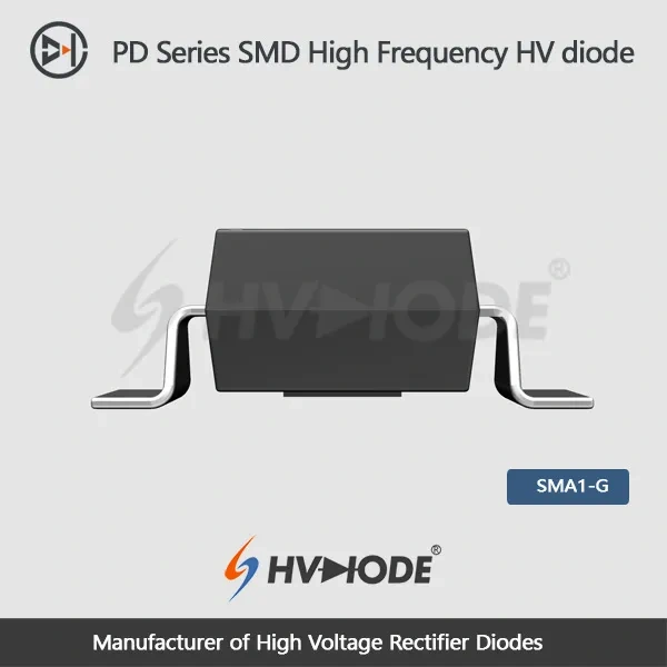
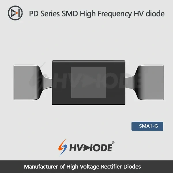
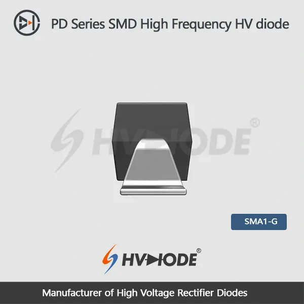

The PD8M is a surface-mount high voltage diode for boards that have to hold off eight kilovolts and still switch quickly. Inside is a silicon chip encapsulated in a high thermal conductivity epoxy compound, housed in a moulded body with gullwing, outer-bend leads. Heat leaves through the body and the two leads rather than through a metal tab. That is the trade this package makes, and it is why layout and cooling conditions carry as much weight as the rating itself. Most buyers are hardware and component engineers at medical imaging, industrial power and high-voltage supply companies, together with repair teams replacing a failed rectifier in existing equipment. - Surface-mount gullwing connection — outer-bend feet sit flat on the pads, so the part runs through the same reflow line as the rest of the board and needs no separate hand-soldering step. - High thermal conductivity epoxy molding — the encapsulant is chosen to move heat out of the chip, which keeps the chip cooler on boards where the diode is packed between other components and has little copper to spare. - Ultra-small package — the compact body frees the board area that creepage and clearance rules demand at 8 kV, which is often the real constraint in a high-voltage layout. - 8 kV reverse rating — repetitive peak and working reverse voltages are both published, giving a clear ceiling for the reverse stress the part is built to take between pulses. - Surge headroom — the data sheet's non-repetitive surge figure covers the start-up and flashover transients that high-voltage supplies see when a tube or a capacitor bank first charges. - Wide operating window — the ambient and storage ranges run well beyond ordinary commercial grades, which leaves margin when the diode sits near a transformer, a tube or another heat source.
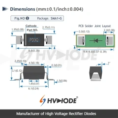
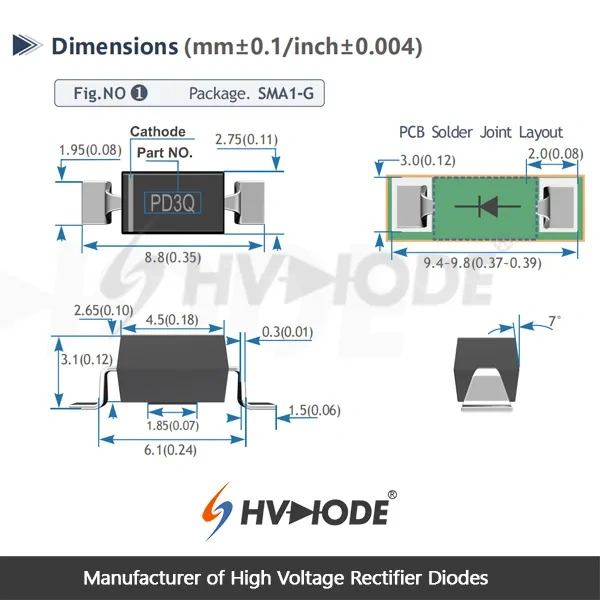
Two parts of the mechanical drawing matter here: the package outline and the PCB solder joint layout. Work from those rather than scaling a product photo, because the gullwing foot needs a pad long enough to leave a fillet at the toe and at the heel, and the body needs clearance at each end so the moulding does not sit on a solder mask ridge.
At eight kilovolts the board around the part is part of the design. Keep the conductor spacing across the top surface generous for your pollution degree and for whatever coating or potting the assembly uses, and think twice before running a ground plane directly under the body. Flux residue, dust and finger oil on the surface between the leads cut the effective withstand of an SMD high voltage diode far more than they would on a low-voltage part.
Thermally, the epoxy body and the two leads are the whole heat path. Give each pad a copper area wider than the foot itself and, where the board has inner layers, stitch that copper down with vias. A diode carrying this much average forward current runs noticeably cooler with that spreading than on a minimum-size pad, and the difference shows up as a lower case temperature rather than a lower reading on a data sheet.
Boards that carry more than one PD series part can use a single land pattern, so a move from one current grade to another does not force a re-spin. Check that before you panelise: it is the cheapest way to keep an 8 kV product family on one PCB.
The PD series holds one package size across its grades, and that is the practical argument for staying inside it. A board laid out for one member usually takes another without moving pads, and a product family spanning several output ratings can share a single PCB.
Within the 8 kV class the real choice is current. This part carries 450 mA average forward current; the PD8J uses the same 8 kV rating and the same body but is rated at 300 mA. If your load stays comfortably under 300 mA, either part works electrically and the decision comes down to availability. If you are running near 450 mA, only the higher grade leaves margin, and swapping down because the footprint matches is not a safe substitution.
When you replace an existing rectifier, compare five things first: repetitive peak reverse voltage, average forward current at your case condition, recovery time, package and lead form, and the temperature the surrounding board actually reaches. A candidate that matches on voltage but is slower on recovery will run hotter in a fast-switching stage; one that matches on recovery but has a shorter lead span may not reach your pads.
As high voltage diode manufacturers we can look at a photographed or scanned old part and say whether a PD part is a genuine equivalent, but the release decision should rest on your own qualification data. Send the old marking, the working voltage and the current waveform, and ask for the comparison in writing.
Two cautions before you commit. Do not fit a lower-current grade simply because it is in stock — thermal margin disappears quickly at high ambient. And do not assume that every fast recovery diode with the right voltage behaves identically in a multiplier stack, because recovery and leakage both change how the stage balances.
| Parameter | Test conditions | Value |
|---|---|---|
| Repetitive peak reverse voltage (Vrrm) | Ta = 25 °C, Ir = 1.0 µA | 8 kV |
| Peak working reverse voltage (Vrwm) | Ta = 25 °C, Ir = 1.0 µA | 8 kV |
| Average forward current (If(AV)) | 50 Hz half-sine, resistive load, Tbreak = 50 °C | 450 mA |
| Reverse recovery time (Trr) | — | 75 ns |
| Surge forward current (Ifsm) | 0.01 s half-sine, 50 Hz | 10 A |
| Forward peak voltage (Vfm) | — | ≥ 9.1 V |
| Reverse peak current (Irrm1) | Ta = 25 °C, VRM = VRRM | 1.0 µA |
| Reverse peak current (Irrm2) | Ta = 100 °C, VRM = VRRM | 20.0 µA |
| Operating ambient temperature (Ta) | — | −55 to +175 °C |
| Storage temperature (Tstg) | — | −55 to +150 °C |
| Package | SMA1-G, gullwing (outer bend) leads | Surface mount |
| Series | PD series | Shared package size |
Selection starts with your circuit, not a catalogue number: tell us the working voltage, load current, switching frequency and ambient cooling conditions, and our engineers will match a model from our range and explain the margin left in the design. Each model ships with its datasheet, package drawing and installation guide, and we stay available for mounting and soldering questions, start-up checks and fault finding when an existing part runs hot or fails early. Orders run from about 7 days to 6 months depending on quantity, usually by international express.
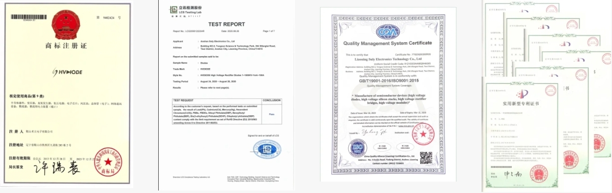
- Manufacturer since 2008 — the company behind HVDIODE is Anshan Suly Electronics Co., Ltd., which has concentrated on semiconductor high-voltage rectifier components since 2008 rather than adding them to a general catalogue. - ISO 9001 quality management — the system is certified to ISO 9001, so assembly, test and release follow documented procedures with records behind them. - RoHS and SGS testing — the manufacturing companies in the group hold EU RoHS certification and SGS global testing certification; ask for the current certificates when you need them for a supplier file. - Parameter testing on dedicated benches — leakage current, recovery time, surge and forward voltage are measured on multi-voltage-level high-voltage test benches, a high-temperature and voltage-bias bench, high and low temperature chambers, a leakage current tester, a TRR tester and a surge impact bench. - Built and tested in-house — as high voltage diode manufacturers we keep assembly and testing under our own roof, so a specification question or a deviation request reaches the people who make the part. - R&D that answers application questions — long-standing cooperation with universities and research institutions means questions about recovery, leakage and thermal behaviour get an engineering answer instead of a data sheet quote. - Repeat supply — universities, research institutions and industrial OEMs buy our high voltage diodes long term, in a niche where the same engineers come back for the next voltage grade.