
Categories
  • PF25F SMD high voltage diode 25KV,100mA, 75nS
  • PF25F SMD high voltage diode 25KV,100mA, 75nS
  • PF25F SMD high voltage diode 25KV,100mA, 75nS
  • PF25F SMD high voltage diode 25KV,100mA, 75nS
  • PF25F SMD high voltage diode 25KV,100mA, 75nS
  • PF25F SMD high voltage diode 25KV,100mA, 75nS
  • PF25F SMD high voltage diode 25KV,100mA, 75nS
  • PF25F SMD high voltage diode 25KV,100mA, 75nS

PF25F SMD high voltage diode 25KV,100mA, 75nS

Products Main features:
1、SMD connection.
2、High thermal conductivity epoxy compound molding.
3、Fast recovery time for high efficiency.
4、Gullwing(Outer Bend) shapes.
5、Ultra small size package
6、Fast recovery PF Series are the same package size.
  • Description

  • data sheet

  • Installation Guide

Product Overview

  • The PF25F is a surface-mount high voltage diode rated at 25 kV repetitive peak reverse voltage, 100 mA average forward current and a 75 ns recovery time. It is built in the PF series: a moulded epoxy body, gullwing terminals bent outward for soldering, and a package small enough to sit among the other components of a high-voltage board instead of occupying a leaded axial position. The rating combination is the part's character. Twenty-five kilovolts is a lot of reverse margin for a body this size, and the 100 mA forward rating suits circuits where the load is a bias rail, a multiplier stage or a low-current rectifier rather than a power output. Designs that settle on this model usually have a high DC potential to hold off in a small space — an imaging supply, an instrument bias board, a detector chain — and they care more about stable leakage and honest spacing than about carrying amps. On the board the part reads simply: flat black moulding, a silver band marking the cathode, wide metal end terminals. The gullwing shape leaves a visible solder fillet on each side after reflow, which makes inspection quick and gives a joint with some compliance as the board cycles in temperature. What the circuit really asks of it is consistency. Leakage is specified at two temperatures because that is where high-voltage designs get caught out, and recovery is specified because rectification in a switched supply depends on it. The moulding, the terminal shape and the temperature range all exist to keep those two numbers stable in service. The compact package supports integration into existing layouts, and the diode is suitable for use in insulating oils, gases, or exposed air.
  • Industrial automation and process equipment — rectifier stages inside high-voltage supplies for fast-response machinery. Sealed cabinets run warm with no airflow, so the moulded body's thermal path and the wide operating range do most of the work.
  • Compact power supplies — switch-mode designs that must fit a shallow enclosure, where the gullwing package lies flat beside the transformer and controller, and the 25 kV rating leaves margin on a supply that generates a high DC output.
  • Renewable energy conversion — high-voltage sections of solar and storage conversion equipment, where the diode rectifies inside the conversion chain and the compact body fits the space already allocated on the board.
  • Aerospace and defence electronics — instrument supplies and detector bias circuits that must hold their characteristics across a wide ambient range and are often encapsulated, so both the temperature window and compound compatibility matter.
  • Medical imaging — bias and rectifier positions inside imaging equipment, where drifting leakage shows up as noise in the image and a failed high voltage diode means a service call. Stable leakage at elevated temperature is the property specified here.
  • High-voltage test and NDT equipment — X-ray and inspection sources with high-frequency switched supplies, where recovery behaviour and the ability to work immersed in insulating oil both come into play.
Close-up of black surface-mount diode with silver terminals

Product Advantages

  • Fast recovery keeps switching losses where they belong — the recovery time is short enough for the switching frequencies used in compact high-voltage supplies, so less energy is turned into heat at each transition and the components around the diode run cooler.
  • A thermal path through the moulding — the epoxy compound is selected for thermal conductivity, moving junction heat into the body and the board. In a sealed cabinet or a potted module with no airflow, that determines whether the diode runs at its rated current or has to be derated.
  • A conservative current rating for this voltage class — 100 mA average forward current at a 50 °C break temperature leaves room for the inrush of a capacitor-charging front while keeping the body small. Check your own duty cycle against the datasheet condition before you sign the design off.
  • Terminals chosen for inspection — the outer-bend gullwing shape produces a visible solder fillet on both sides of the joint, which is what an inspector needs on a high-voltage assembly where a partial joint becomes a hot spot later.
  • One package across the PF series of high voltage diodes — a board laid out for one rating can usually be re-populated with another, so increasing voltage margin late in a project does not automatically mean a new layout.

Test & Verification

What is verifiedTest bench
Reverse voltage at rated levelMulti-voltage level high-voltage test bench
Leakage current at 25 °C and at elevated temperatureLeakage current tester
Recovery time (Trr)TRR tester
Surge current withstandSurge impact test bench
Forward and reverse voltage parametersVf / Vr parameter simulation bench
Long-term stability under biasHigh-temperature and voltage bias test bench
Behaviour across the operating and storage rangeHigh and low temperature test chamber

Installation, Potting & Insulation

  1. Match the pads to the package drawing before you start — terminal spacing, body keep-out and the cathode orientation on the silkscreen. The PF series shares one footprint, so a board laid out for another rating can usually be re-populated, but the drawing is what you check against.
  2. Set the high-voltage spacing at layout. Creepage and clearance between the two terminals and to any nearby trace are set by your working voltage and pollution degree, not by the diode's rating; on high-voltage boards, spacing causes more failures than the components do.
  3. Print paste and place the part. The flat body and wide end terminals sit squarely on the pads and self-centre during reflow, so placement is forgiving compared with fine-pitch devices.
  4. Reflow to the profile your paste and board specify. The moulded body is built for surface-mount assembly; what it does not enjoy is a soldering iron held on a terminal, which puts local heat into the epoxy and the internal joint at the same time.
  5. Clean, dry and inspect before any encapsulation. Flux residue left on a high-voltage board is a leakage path that grows with humidity, so clean the assembly, dry it thoroughly, then check the fillets and the polarity band under magnification.
  6. Apply the insulating adhesive or potting compound. Its two jobs are dielectric — raising the breakdown strength around the body, the terminals and the joint — and thermal, carrying heat out of the package into the assembly. Choose a compound rated for your working voltage and degas it before use so no air is trapped against a terminal.
  7. Cure to the compound supplier's schedule rather than a shortened one, then inspect for voids under the body and around the terminals. Voids and under-cured compound are the usual causes of partial discharge in potted high-voltage assemblies, not the diode itself.
  8. Test the finished assembly at the working voltage, and again at operating temperature if the module runs warm. A cold pass with a hot failure supports spacing or potting rather than to the component.

Polarity & Orientation Checks

  • The silver band on the moulded body is the cathode. Check that band against the silkscreen before the board enters reflow, and look again after cleaning, because flux residue and compound bleed can dull it enough to be misread under a bench light.
  • Carry the orientation on the assembly drawing, not only on the board. A drawing that states the band direction survives a stencil revision or a new operator; silkscreen alone often does not.
  • Do not try to prove polarity with an ordinary multimeter diode test. Forward peak voltage on this model is ≥15.6 V, far above what a handheld meter applies, so a blank reading tells you nothing about a good high voltage diode. Use a curve tracer, a high-voltage bench, or a reverse leakage check at a safe fraction of the rated voltage.
  • In a rectifier chain, a reversed device appears as a forward-conducting path when the string is tested in the reverse direction. That single check catches most assembly errors before power is ever applied.
  • Inspect both gullwing joints. A terminal that lifted during reflow leaves an open circuit in the forward direction and a poor thermal path into the board; the fillet on each side should be visible and even.
  • Before potting, record the orientation and photograph the assembly. Once the compound cures the band is buried, and any later field replacement depends on that record.
  • When desoldering a used part, mark the band direction first. The body is symmetrical apart from the band, so a removed diode gives no clue about which way it sat.

Specifications

ParameterSymbolUnitTest conditionsValue
Repetitive peak backward voltageVrrmkVTa = 25 °C, Ir = 1.0 µA25
Peak working backward voltageVrwmkVTa = 25 °C, Ir = 1.0 µA25
Average forward currentIf(AV)mA50 Hz half-sine wave, resistance load, Tbreak = 50 °C100
Backward recovery timeTrrns—75
Surge forward currentIfsmA0.01 s half-sine wave, 50 Hz10
Forward peak voltageVfmV—≥15.6
Backward peak current at 25 °CIrrm1µAVRM = VRRM1.0
Backward peak current at 100 °CIrrm2µAVRM = VRRM20.0
Operating ambient temperatureTa°C—-40 to +175
Storage temperatureTstg°C—-40 to +150
Package——Surface mount, gullwing (outer bend) terminalsSMD

Current Ratings & Series Limits

  • The 100 mA figure is an average forward current, taken on a 50 Hz half-sine wave into a resistive load with the break temperature held at 50 °C. It describes how much heat the body can hand to its surroundings over time, not a ceiling on every pulse that crosses the junction.
  • Short events are checked against a different number. The surge forward current rating is 10 A for a 0.01 s half-sine pulse, so a capacitor-charging inrush or a fault spike belongs against that limit rather than being squeezed under the average rating, which would over-derate the part and push you toward a larger body than the job needs.
  • The usable continuous current follows your cooling. Open air on a board relies on copper area and convection; a potted module, an oil-immersed assembly or a sealed cabinet changes the heat path, and with it the current the same body can carry. Compare your own duty cycle and mounting with the datasheet condition before the design is signed off.
  • Two diodes in series do raise the reverse voltage, but they do not share it equally by themselves. Reverse leakage varies from device to device and climbs steeply with temperature — 1.0 µA at 25 °C against 20.0 µA at 100 °C on this model — so the device with the lower leakage carries more than half of the applied voltage unless the network forces a division.
  • A series string needs a sharing network and a full-length spacing plan. A resistor or capacitor across each diode makes the division predictable, and creepage has to be laid out for the total working voltage across the whole string, not for one body.
  • Above 25 kV, change family instead of stacking more surface-mount parts. The range also includes axial high voltage diodes, high-voltage silicon stacks and complete rectifier assemblies, which are built and tested as one unit rather than depending on matched leakage between discrete components.
  • If you are weighing a series pair against a single higher-voltage part, send the working voltage, load current and cooling method; the comparison turns on your circuit numbers, and it is quicker to settle with them in hand.

Range & Manufacturing Background

The PF family runs from 15 kV to 25 kV, and the current rating moves in the opposite direction to the voltage. At the top, this model holds 25 kV at 100 mA; PF25H holds the same 25 kV with 200 mA for circuits that need more current; at 20 kV, PF20J carries 300 mA and PF20H 200 mA; at 15 kV, PF15H carries 200 mA. Read the ladder that way and the choice becomes mechanical: take the lowest voltage rating that still leaves sensible margin, then the lowest current rating that covers the load, because leakage and heat both rise as the die grows.

Behind the series is HVDIODE, the brand of Anshan Suly Electronics, which has produced semiconductor high-voltage rectifier components since 2008 for universities, research institutes and equipment makers in China and abroad. The catalogue covers surface-mount and axial high voltage diodes, high-voltage silicon stacks, rectifier bridges and complete rectifier assemblies, which matters in practice: a high-voltage supply rarely needs a single diode type, and buying the rectifier chain from one source keeps test conditions and documentation consistent from part to part.

High voltage diode manufacturers are judged on what their parts do at the top of the voltage range, so that is where the test programme sits. Components are assembled with high thermal conductivity epoxy moulding, checked on benches purpose-built for high voltage rather than general-purpose component testers, and released against the same limits printed in the datasheet. The quality management system is certified to ISO 9001, and the company's facilities hold RoHS and SGS testing certification.

Factory collage with buildings, production rooms and bulk rectifier diodes

Ordering & Delivery

  1. Send the model, the quantity and the conditions of your circuit — working voltage, load current, and whether the assembly is air-cooled, potted or oil-immersed. If you are replacing an existing part, include the markings from the old component; in this family a single letter change moves the current rating.
  2. We reply with price, lead time and shipping terms for that quantity. International express is our standard method; tell us at the same point if your receiving department needs a different arrangement.
  3. Confirm the packing format your line can handle — quantity per reel or tray — so the parts arrive ready for the pick-and-place machine instead of being re-packed by hand.
  4. Ask for the datasheet, package drawing and installation guide with the quotation. When you compare high voltage diode manufacturers, the documentation often matters as much as the price; we send both together so incoming inspection can check delivered parts against the limits the design was signed off against.
  5. Agree payment terms and Incoterms in writing on the order confirmation before production is scheduled.
  6. Keep the full model designation on repeat orders. A substitute can fit the board perfectly and still be the wrong voltage rating — a common trap when high voltage diodes are second-sourced under time pressure.

Technical Support & Model Matching

Selection starts with your circuit, not a catalogue number: tell us the working voltage, load current, switching frequency and ambient cooling conditions, and our engineers will match a model from our range and explain the margin left in the design. Each model ships with its datasheet, package drawing and installation guide, and we stay available for mounting and soldering questions, start-up checks and fault finding when an existing part runs hot or fails early. Orders run from about 7 days to 6 months depending on quantity, usually by international express.
FAQ

Does the 100 mA rating cap the peak current through the diode?

Not directly. It is an average forward current, specified on a 50 Hz half-sine wave with a resistive load at a 50 °C break temperature. Short pulses are covered separately by the surge forward current rating, which is given for a 0.01 s half-sine pulse. Use the average figure against your cooling arrangement and the surge figure against your worst transient, and the part is being worked as specified. The average figure is the one high voltage diode manufacturers quote most often, and the one most often misread as a peak limit.

Can two of these be connected in series for a higher reverse voltage?

They can, but series operation is a voltage-sharing problem rather than a simple doubling. Two devices in series will not divide the reverse voltage equally unless their leakage is matched and the network is designed for it — normally with a resistive or capacitive divider across each diode. Below 25 kV, a single device in a properly spaced and potted assembly is the simpler and more predictable answer. If your working voltage sits above the SMD range, send us the circuit conditions and we will point you to the right family.

Does it have to be potted, or can it run in open air?

Both environments are used, and so is immersion in insulating oil or gas. What changes is the margin. In air, the body and terminals need clean, dry surfaces and generous creepage to nearby conductors; potting or oil raises the dielectric strength around the joint and also carries heat out of the package. Decide which one your assembly uses early, because it changes your spacing and your thermal calculation before any of it is committed to a board.

How do I identify the cathode on the assembled board?

The silver band on the moulded body marks the cathode. Match it to the silkscreen before reflow, then look again under magnification after cleaning — a reversed high voltage diode in a rectifier usually fails at first power-up instead of showing up as a marginal reading.

The datasheet lists both Vrrm and Vrwm at 25 kV — which one is the design limit?

Vrrm is the repetitive peak reverse voltage, the level the device is expected to hold off cycle after cycle, and Vrwm is the peak working reverse voltage; both are quoted at 25 °C with reverse current at 1.0 µA. Design to the repetitive value with margin for switching transients, and remember that reverse leakage climbs with temperature — the 25 °C reading is not the worst case.

The selection of high-voltage diodes is closely related to their usage environment。

1. Used in insulating oil. (Recommended)
2. Used in insulating gases. (Recommended)
3. Secondary packaging use. (High requirements for heat dissipation and other parameter performance of components)
4. Use in exposed air or add air cooling. (If the size of the high-voltage diode is small, it is easy to discharge, and the heat dissipation performance is average.)

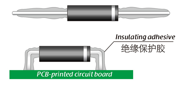
For high-voltage diodes used in exposed air, it is recommended to install them with insulated electrodes at both ends.


Common treatment methods for surface adhesive insulation:

Characteristics of insulation adhesive material:

1. Silicone material usually presents a transparent and elastic rubber state after curing, which is more effective in shock resistance and can also withstand severe stress changes caused by large high and low temperature changes (-40 ° C~200 ° C).

2. Acrylic materials typically exhibit a transparent and hard coating after curing, with low moisture absorption and fast curing time, as well as excellent wear resistance and insulation.

3. After curing, Urethane material usually presents a transparent and hard coating, which has superior wear resistance and good moisture resistance. Its performance is particularly stable in low temperature environments, but it is less resistant to high temperatures.

4. The coating material based on epoxy is very sturdy and usually opaque, with good moisture and moisture resistance. Its resistance to chemical corrosion and wear is also very good. In addition, epoxy also has good dielectric properties.

Here, suitable insulation adhesive materials can be selected based on the different usage situations of engineers.

  • PF25F SMD high voltage diode 25KV,100mA, 75nS
  • PF25F SMD high voltage diode 25KV,100mA, 75nS
  • PF25F SMD high voltage diode 25KV,100mA, 75nS
  • PF25F SMD high voltage diode 25KV,100mA, 75nS
Leave a message
Name
Email *
Message
Verification Code *
Click to verify
We use Cookie to improve your online experience. By continuing browsing this website, we assume you agree our use of Cookie.